- Foreword
- Functions
- How to connect
- How to operate
- Project diagrams
- PC software
- EZ-KIT lite firmware
- User manual for the DSP-10 transceiver
- W7PUA's site of the DSP-10
- More DSP-stuff of your interrests...
- Pictures of my DSP-10 project
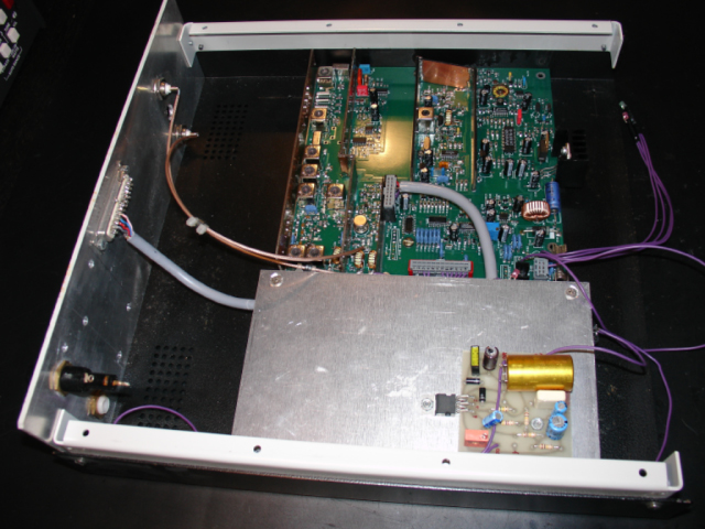
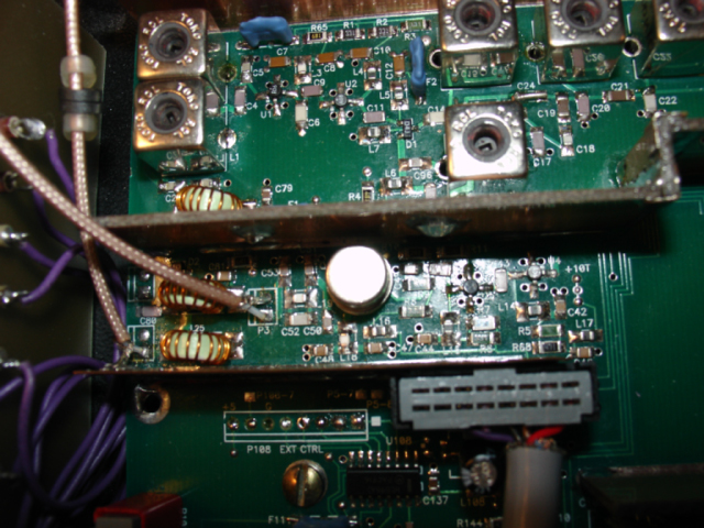
My DSP-10 transceiver project.
In the front is an audio amplifier mounted at
the top of the RF incapsulated EZ-KIT Lite
ADSP-2100 board from Analog Device (TM).
In the background is the DSP-10 RF board.
This is my DSP-10 transceiver project - a Software Defined Radio (SDR). The project is build of three parts. The EZ-KIT Lite ADSP-2100 based Digital Signal Processor from Analog Device, a simple audio amplifier board and the DSP-10 board. The EZ-KIT Lite is a ready build DSP board that "just" needs some DSP firmware. The DSP-10 RF board is based on a construction from W7PUA.
The DSP-10 transceiver is working as a Software Based Radio (SBR) and is controlled by a peice of software by on a personal computer.
Connect a personal computer to the RS-232 connector at the rear, an antenna for 144-146 MHz to the antenna connector at te rear, a speaker to the speaker jack at the rear, a microphone to the microphone connector at the front and 12V of power. Start the DSP-10 software on the connected computer and you are you are simply running the DSP-10 transceiver.
Se "User manual for the DSP-10 transceiver" bellow at this home page
- The DSP-10: An All-Mode 2-Meter Transceiver Using a DSP IF and PC-Controlled Front Panel -- Part 1
- The DSP-10: An All-Mode 2-Meter Transceiver Using a DSP IF and PC-Controlled Front Panel -- Part 1 from ARRL's home page
- The DSP-10: An All-Mode 2-Meter Transceiver Using a DSP IF and PC-Controlled Front Panel -- Part 2
- The DSP-10: An All-Mode 2-Meter Transceiver Using a DSP IF and PC-Controlled Front Panel -- Part 2 from ARRL's home page
- The DSP-10: An All-Mode 2-Meter Transceiver Using a DSP IF and PC-Controlled Front Panel -- Part 3
-
The DSP-10: An All-Mode
2-Meter Transceiver Using a DSP IF and PC-Controlled Front Panel -- Part 3 from
ARRL's home page
- More DSP goodies from the ARRL article data base
- EZ-KIT Lite firmware (running on the ADSP-2181) (uhf3ez25.zip)
- EZ-KIT Lite firmware (running on the ADSP-2181) from W7PUA's home page
- EZ-KIT Lite firmware (running on the ADSP-2185) (uhf3x25.zip)
- EZ-KIT Lite firmware (running on the of ADSP-2185) from W7PUA's home page
- EZ-KIT Lite firmware ready to burn into a 27c512 ERPOM replacing the original EPROM in the EZ-KIT Lite (uhf3hx25.zip)
- EZ-KIT Lite firmware ready to burn into a 27c512 ERPOM replacing the original EPROM in the EZ-KIT Lite from W7PUA's home page
- EZFAST shareware is a fast loader used to load the uhf3ez25.zip into the EZ-KIT lite after power ON the EZ-KIT Lite board (ezfast3a.zip)
- EZFAST shareware is a fast loader used to load the uhf3ez25.zip into the EZ-KIT lite after power ON the EZ-KIT Lite board from W7PUA's home page
- Description of the commands and responses between the EZ-KIT Lite and the personal computer
- Description of the commands and responses between the EZ-KIT Lite and the personal computer from W7PUA's home page
- Description of the PUA43 mode
- Description of the PUA43 mode from W7PUA's home page
- Ver 3.10 PC SOURCE CODE and Ver 2.5 DSP SOURCE CODE
- Ver 3.10 PC SOURCE CODE and Ver 2.5 DSP SOURCE CODE from W7PUA's home page
User manual for the DSP-10 transceiver
You can find a lot more information at W7PUA's home page...
More DSP-stuff of your interrests...
- A Software-Defined Radio for the Masses, Part 1 (QST)
- A Software-Defined Radio for the Masses, Part 2 (QST)
- A Software-Defined Radio for the Masses, Part 3 (QST)
-
A Software-Defined Radio for the Masses, Part 4 (QST)
- A Software-Defined Radio for the Masses, Part 1 (QST) - ARRL
- A Software-Defined Radio for the Masses, Part 2 (QST) - ARRL
- A Software-Defined Radio for the Masses, Part 3 (QST) - ARRL
- A Software-Defined Radio for the Masses, Part 4 (QST) - ARRL
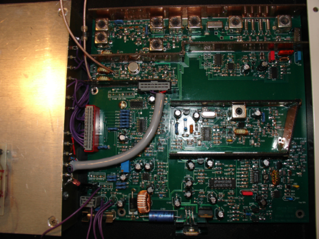
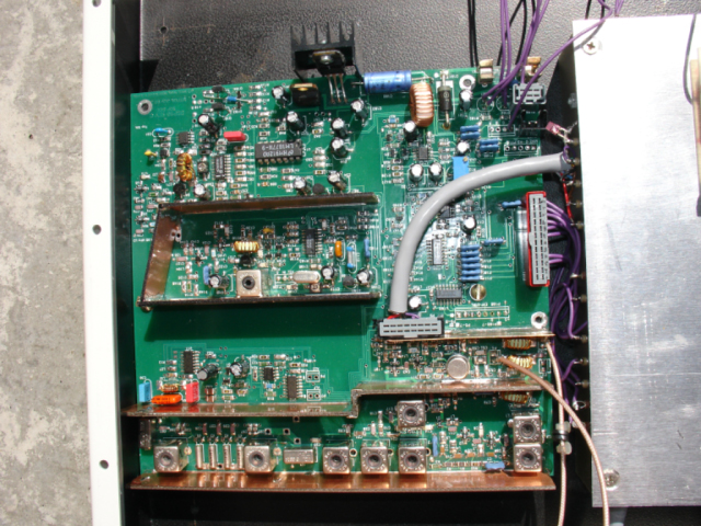
The RF-incapsulated EZ-KIT Lite at the left and
the DSP-10 RF board at the right.
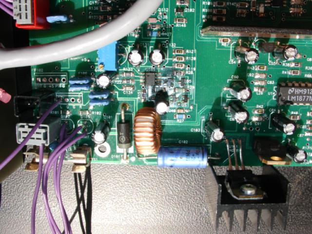
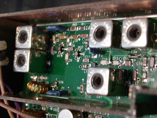
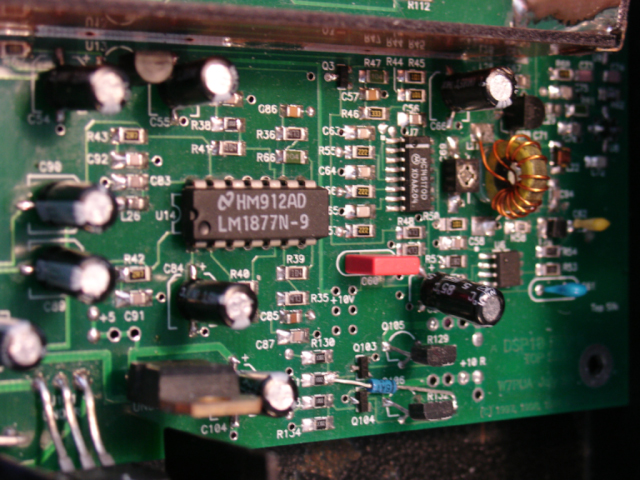
The RF input/out stage of the DSP-10 RF board
The 200 mW output stage of the DSP-10 RF board
The RF input of the DSP-10 RF board
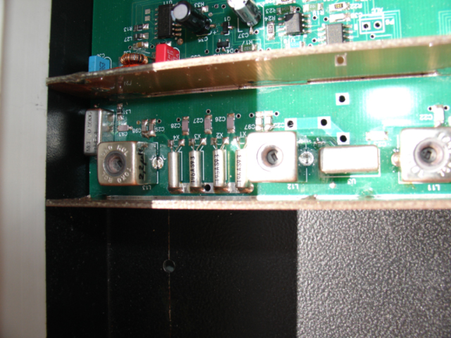
The RF input crystal filtering
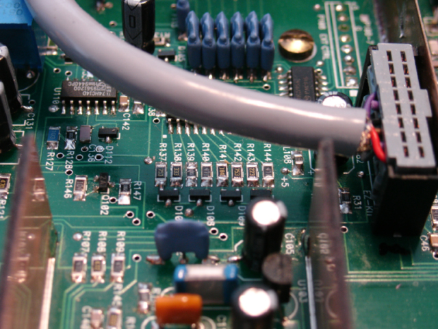
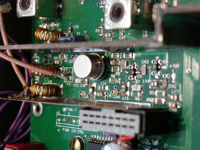
The interface between the EZ-KIT Lite and the DSP-10 RF board
The PLL part of the DSP-10 RF board